
ZRELY1 - Reliability of Logic Circuits
Combinational logic circuits are part of all modern CPUs and other electronic means of information processing. These processors are widely used and constantly grow in complexity. Number of transistors in a modern CPU has exceeded 2 billion?. And it looks like this growth does not tend to stop. At the same time, technological processes of processor production shrink. Transistors become smaller and more vulnerable to external influences. And now, even far from the strongest external radiation or magnetic field can lead to short-term changes in the logical values of microelectronic circuits. This problem is especially acute in space systems and other systems critical to reliability. In this problem, we pose the question, how to make the circuit more resilient to external influences knowing its logic? Your task is to develop an algorithm for creating such a reliable circuit.
Let a logic circuit without feedback or memory elements is given, consisting of the following 6 elements:
| Name | Description | Operation | Figure |
|---|---|---|---|
| INV | inverter | OUT=!A | 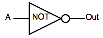 |
| AND | logical «AND» | OUT=A&B | 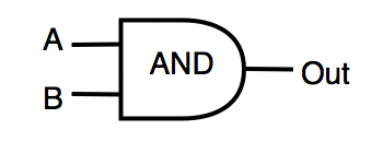 |
| OR | logical «OR» | OUT=A|B | 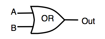 |
| NAND | inverted AND | OUT=!(A&B) | 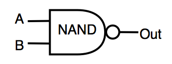 |
| NOR | inverted OR | OUT=!(A|B) | 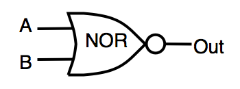 |
| XOR | exclusive «OR» | OUT=A^B | 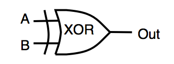 |
The circuit is affected by environmental noise changing gate logical value to the opposite with a certain probability. Your task is to construct a circuit which has the same logic function as the original one, but is less prone to failures. Under the terms of the problem the circuit that you construct should exceed the initial area no more than "K" times .
One of the parameters which characterize failure tolerance of logic circuits is COF – “Total circuit failure resistance factor”. COF is calculated as the ratio of the number of correct results of circuit performance (all circuit outputs must have correct value) to the total number of the performed tests. Accordingly, for the most reliable circuits COF tends to 1.
Every logic gate of the circuit is characterized by the following parameters: S – gate area, p – failure probability (in percent) under current external conditions.
Input data
The first line shows Z – the number of tests (Z < 400). This is followed by Z tests .
The first line of each test shows the number K (2.0 ≤ K ≤ 20.0) - maximum circuit area redundancy.
The following six lines contain two numbers each: area S (1 ≤ S ≤ 100) and failure probability q (0 ≤ q ≤ 20) in percent, Parameters of each of the logic gates are given in the following order: INV, AND, OR, NAND, NOR, XOR.
The next line shows the number “I” (0 < I < 250) – the number of circuit inputs, followed by I lines, no more than 20 characters each, separated by spaces – the names of the input nodes of the circuit.
The next line shows the number “O” (0 < O < 150) – the number of circuit outputs, followed by O lines, no more than 20 characters each, separated by spaces – the names of the output nodes of the circuit.
Then the number of logic gates in the circuit N (1 < N < 5000) is stated, followed by N lines with the description of each gate.
Description of each gate begins with its type, next come the names of the input nodes, then the name of the output node
Output data
For each test you should present the circuit description of in the following format. In the first line number N (1 < N < 100000) – the number of gates in the resulting circuit. This is followed by N – lines with the gates description. Each gate description begins with its type, next come the names of the input nodes, followed by the name of the output node.
Scoring
The number of scored points Score is summed over all tests. The number of points received for a test is equal to COF value calculated for your circuit. COF is calculated by Monte Carlo method? in two steps:
1) in the first step, the judge determines that your circuit works identically to the original one. The same test sequences (several thousand) are fed to the inputs of both circuits and Boolean values at the outputs of the circuits are compared. If the logical values differ, you get the status of Wrong Answer. Also, the judge checks that the given circuit redundancy was not exceeded.
2) in the second step, the judge will invert the values on your circuit gates randomly with the given probability and compare the output values for your circuit and the benchmark circuit. If at least one of the outputs will be different, «wrong answers» counter will be increased. Formula used for calculation: COF = (TT - INC)/TT, where:
TT - total number of tests
INC - number of tests, where at least one output of the circuit manifested error
From final score we extract C=276 points, which somewhere equal default soultion. If final score lower than 276 it'll recieve 0 points.
Example
Input data:
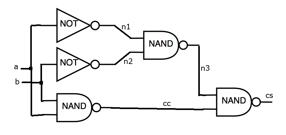
Let logic circuit is given (see the figure). Required redundancy should not be more than 4.1 times. The circuit is based on the library, for which:
INV has area 50 and failure probability 3%
AND has area 60 and failure probability 3.1%
OR has area 60 and failure probability 3.2%
NAND has area 70 and failure probability 3.3%
NOR has area 70 and failure probability 3.4%
XOR has area 70 and failure probability 3.5%
Input file for this task looks as follows:
1
5.1
50.0 3.0
60.0 3.1
60.0 3.2
70.0 3.3
70.0 3.4
70.0 3.5
2 a b
2 cs cc
5
INV a n1
INV b n2
NAND a b cc
NAND n1 n2 n3
NAND n3 cc cs
Output data:
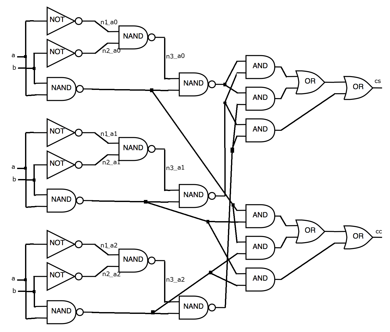
Let our algorithm uses standard triplication technique and selection of a Boolean value which is used on the majority of outputs (Triple Modular Redundancy (TMR)?). In this case, the output file can be written as follows:
25
INV a n1_a0
INV a n1_a1
INV a n1_a2
INV b n2_a0
INV b n2_a1
INV b n2_a2
NAND a b cc_a0
NAND a b cc_a1
NAND a b cc_a2
NAND n1_a0 n2_a0 n3_a0
NAND n1_a1 n2_a1 n3_a1
NAND n1_a2 n2_a2 n3_a2
NAND n3_a0 cc_a0 cs_a0
NAND n3_a1 cc_a1 cs_a1
NAND n3_a2 cc_a2 cs_a2
AND cs_a0 cs_a1 cs_3_0_and_0_out
AND cs_a0 cs_a2 cs_5_0_and_0_out
AND cs_a1 cs_a2 cs_6_0_and_0_out
OR cs_3_0_and_0_out cs_5_0_and_0_out cs_0_or_0_out
OR cs_0_or_0_out cs_6_0_and_0_out cs
AND cc_a0 cc_a1 cc_3_0_and_0_out
AND cc_a0 cc_a2 cc_5_0_and_0_out
AND cc_a1 cc_a2 cc_6_0_and_0_out
OR cc_3_0_and_0_out cc_5_0_and_0_out cc_0_or_0_out
OR cc_0_or_0_out cc_6_0_and_0_out cc
Figure for the resulting file
Scoring:
After simulation this solution will score 0.682661 points.
Useful files:
1) Simple solution C/C++ - program reads the data and prints the circuit as it is, without changes.
2) Judge at C/C++ - program, which is used on the server for evaluation of the solution. Can be used locally to test the effectiveness of your solution.
3) Test data set - a set of 102 test circuits, similar to a set on the server.
hide comments

|
bohdan_23:
2020-05-19 11:12:54
It is said that test data set is similar to one on server. I don't think this is true, as my solution score 58 pts on in (vs 45 of standard solution), but gets 0 pts (i.e. less than standard). Any explanations how this is possible? |

|
Roman Sol:
2015-02-16 14:11:35
Flago, yeah I thought about this coefficient, but tried to avoid complicated scoring system. But now I see you right, psychologically difference between 276.1058 and 295.6856 too small than between 0.1058 and 20.6856 ) I will change it in few days. |

|
Flago:
2015-02-16 14:11:35
Ty for the changes, might give it a fair try now some day :)
|
|
|
Roman Sol:
2015-02-16 14:11:35
The scoring system was changed. Now TT means "total number of tests". Now "trash gate" scenario doesn't work, but the difference between solutions became smaller.
|
|
|
Roman Sol:
2015-02-16 14:11:35
Flago, thank you now I get it ) I probably will change the judge to avoid this. Need to think how to make it. Probably I should consider floating nodes as outputs also. |
|
|
Flago:
2015-02-16 14:11:35
@Roman Sol : Nope, changing the seed might give you some (very) little changes on score but it won't give those result just by adding trash gates. I will give you a concrete exemple of the "trash gate abuse".
|
|
|
Roman Sol:
2015-02-16 14:11:35
Flago, actually I don't get it. Why you recieve better score with trash gates? If you don't have these gates you get correct or incorrect as well. And the probability of error of "usefull" gates stays the same. And the error flag set indpendently for any gate. So I think trash gates only can violate "seed" value for random generator. And you get better score not because of trash invertors, but because of random generator generates other values. |
|
|
Flago:
2015-02-16 14:11:35
Enjoyed this problem.
|
| Added by: | Roman Sol |
| Date: | 2014-08-08 |
| Time limit: | 50s |
| Source limit: | 50000B |
| Memory limit: | 1536MB |
| Cluster: | Cube (Intel G860) |
| Languages: | All except: ASM64 |
 RSS
RSS